July 15, 2011 ( last updated : February 17, 2021 )
10mhz
usb
audio
frequency
One of the projects that I am tinkering with at the moment is the creation of an audio capture device that can be phase locked to an external reference. The primary reason for this is not chasing extremely high quality audio – the contrary in fact, I don’t particularly care for the audio quality. The crucial part in this application is the timeing of when the ADC samples – allowing an almost traceable time stamp to be placed on audio recordings. At the very least there will be minimal long term drift over a long recording, making relative time reconstruction possible.
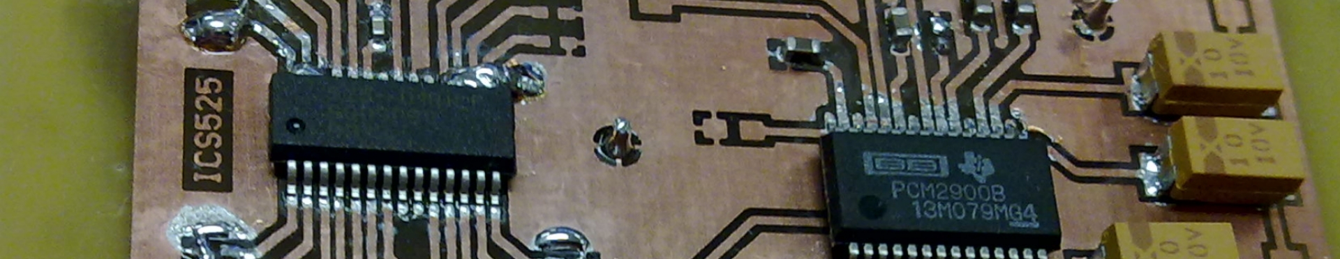
To make this all possible I grabbed a TI PCM2900B USB Audio Codec and started designing a board around this. Normally this IC requires an external 12MHz crystal for operation, which is responsible for generating all the internal clock signals. I have chosen to instead couple the output from an IDT ISC525-01 Clock Generator to the clock input on the PCM2900B.
To make this as useful as possible I have designed assuming an external 10MHz 50 ohm input is used for the clock signal via an SMA connector. This seems to be the de-facto standard for most modern test equipment. The analog input is via a standard 4 pin 2.54mm header (left, right, 2 grounds), and the computer interface is USB.
Whilst none of this is all that ground breaking, I figured that I would share it with the world to help out anyone else that wishes to try this sort of thing.
Anyway, some photos of the prototype:
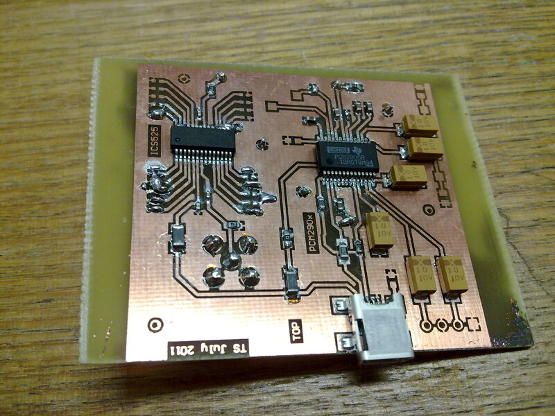
The prototype board fo the USB Sound Card - The chip on the LHS in the photo is the ICS525, and the chip on the right is the PCM2900B. No audio I/O is installed for testing.
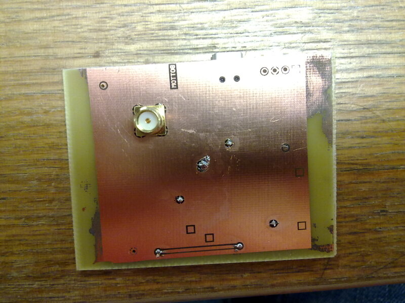
The back of the prototype USB sound card - a couple of vias and an SMA connector.
For testing I haven’t yet used any actual audio I/O. The main purpose was to test the ability to use an external clock with the IC – which worked well. I have now redesigned the board to be considerably smaller (though less versatile) to remove a number of jumpers I included “just incase the datasheet wasn’t quite correct”.
As far as the reference clock goes – I have succesfully used a 0-5V Square Wave output from a function generator, as well as the 1Vpp reference output on the rear of the function generator. Both worked as well as each other (which makes sense, as the input is AC coupled anyway!).
Schematics will come in a post soon, as will possibly a PCB layout for those that want to DIY. The entire project cost is pretty cheap (~$20 for components) and I have intentionally designed the board to be very simple to make.
Originally published July 15, 2011 (Updated February 17, 2021)
Related posts :